3. 3D Survey Collection (v. 1.6.1) Structure
3DSC is composed of several independent panels placed on the sidebar of Blender, within the tab named 3DSC. Panels can easily be arranged by grabbing them from the top right corner.
Remember
The add-on, within the preference menu of Blender, offers a feature that checks for new updates and then asks user for the installation.
3.1. Shifting
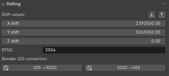
Fig. 3.1 Shifting panel
This panel (Fig. 3.1), which is directly linked to the Importers panel, represents the shifting values (expressed with X, Y, Z) of an object (for example a 2D/3D survey) imported in Blender. Shifting values indicate the translation of an imported 2D survey or 3D object respect to absolute coordinates. On the lower part of the panel, the line EPSG indicates the Reference System (RS) whom 2D and 3D objects, imported in the Blender file, will refer to.
Remember
In order to visualize georeferenced 3D models in Blender, as the ones obtained with photogrammetry, it is strongly suggested to export them with the same shift used in 3DSC and BlenderGis.
To insert shift values in Blender two modes are available: manual and automatic.
Manual mode implies that user insert manually both the coordinates and the EPSG code.
On the contrary, Automatic mode (RECOMMENDED) implies that a SHIFT.txt file is automatically read by 3DSC (ONLY if the file is placed in the folder where the .blend file is saved) and, instantly, shift coordinates will appear within the Shift values lines. To use this automatic mode, press the import shift coordinated from file, on the right corner of the panel, and locate the SHIFT.txt file.
Remember
The SHIFT file is a simple .txt file which contains only one line of data (EPSG:: code X Y Z) here an example:
EPSG::3004 2392800.00 5069900.00 0
By pressing the Export Shift values button, the shift panel allows to export shift coordinates (.txt format) for different purposes.
In order to easily use georeferenced data within Blender it is necessary to set the same SHIFT coordinates also in BlenderGIS (RECOMMENDED). As already mentioned for 3DSC, this important step for BlenderGis can be accomplished in two ways: manual and automatic.
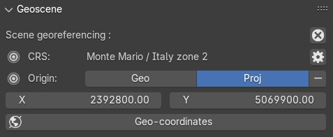
Fig. 3.2 The Geoscene panel of BlenderGIS
Manual mode implies that user manually inserts data (coordinates and EPSG) within the Preferences of BlenderGIS. Then, to confirm this information, user must set the RS and the shift coordinates in the View tab, located on the Sidebar of Blender, within the panel Geoscene (Fig. 3.2). In the Preferences of BlenderGis, before setting the shift coordinates, user must set the correct RS by pressing the add button.
Automatic mode involves the use of an automatic procedure that imports shift data from 3DSC to BlenderGIS. In the Shifting panel of 3DSC, it is possible to activate this option by pressing the 3DSC->GIS button. At the end of this process, it is recommended to control in the Geoscene panel, located in the View tab of the sidebar of Blender, if data are correctly inserted.
If SHIFT coordinates have been previously set up in BlenderGIS, by pressing the GIS->3DSC button all the SHIFT data will be setting up in 3DSC.
Remember
Before saving the file, it’s recommended to check if SHIFT data are synchronized between 3DSC and BlenderGIS.
After shift data has been correctly inserted and an empty Blender file has been setting up and saved, user can easily import georeferenced data by using both 3DSC or BlenderGIS import options.
3.2. Importers
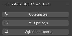
Fig. 3.3 Importers panel
Remember
To import georeferenced data in Blender it is important to set the SHIFT data, see the Shifting section.
This panel (Fig. 3.3) allows to import in Blender three different types of data: coordinates, objects and cameras.
By clicking the Coordinates button user can import a 2D survey (.csv or .txt) in relative or absolute coordinates.
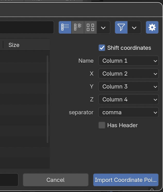
Fig. 3.4 Option of the Importers panel
In the import window, user must: first, locate the appropriate file; second, after pressing the Toggle Region button (the one with a gear on the icon, placed on the right side of the window) associate the first 4 columns of the coordinates file with the equivalent values (name, X, Y, Z) of the selected file (.csv or .txt) and define the separator (comma, space, semicolon, Fig. 3.4).
In the first case, by clicking the Coordinates button user can import in Blender 2D point (such as .csv files) of both relative and absolute coordinates. On the menu which appears on the right side of the window, user can associate the first 4 columns of the coordinates with the correspondent values (name, X, Y, Z) and then define the separator (comma, space, semicolon). To visualize absolute coordinates within Blender, user must flag Shift coordinates button and 3DSC will automatically shift the file. The options Shift coordinates and Has header, respectively on the top and on the lower part of the right side of the Toggle Region window, allow to: force 3DSC to consider the SHIFT coordinates (if the 2D survey is georeferenced and if the SHIFT has previously set up on 3DSC and BlenderGis) and ignore the first line of the selected file (if a header is presented).

Fig. 3.5 Option of the Importers panel related to objects
By clicking on the Multiple objs button 3DSC allows to import several objects with a single command. In the import window, user must:
locate the appropriate file;
select the correct options on the right side of the window (default option allow to successfully import the obj file). If the obj file are not Z Up and Y Forward oriented, user can choose the correct orientation by exploring the corresponding drop-down menu (Fig. 3.5).
The option shifting coordinates, if selected, allow to import georeferenced data with an associated SHIFT.txt file.
Remember
By default, when objects are imported into Blender using the Importer tool of 3DSC, geometries are displayed as Bounds. To change this display mode, select the Object tab, in the Blender’s Properties panel, then, in the Viewport Display panel, select Display as -> Textured to visualize the objects with their materials.
Remember
It is recommended to import objects without textures if they need to be textured later outside Blender.
3.3. Exporters
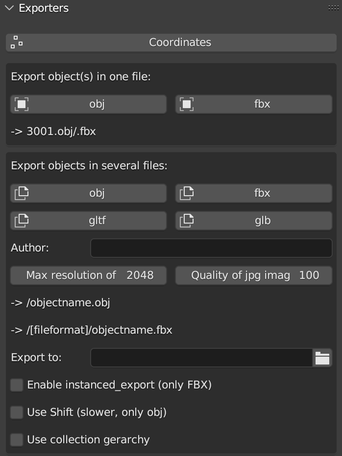
Fig. 3.6 Exporters panel
This panel (Fig. 3.6) is divided in three sub-sections: Coordinates, Export object(s) in one file and Export objects in several files.
The Coordinates button allows to export every type of coordinates (.txt file) associated to an object (such as: points, meshes, cameras etc..) imported in the 3D space of Blender. After pressing the button, the export window will appear.
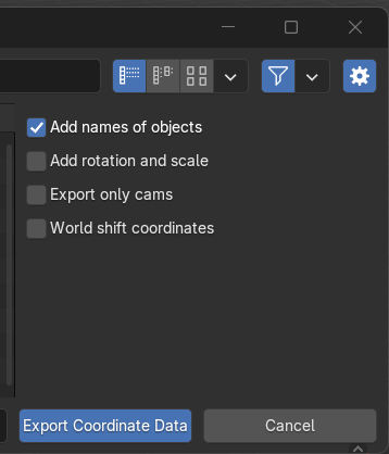
Fig. 3.7 Exporter window options
To customize the export of these data the user can flag specific options (Add names of objects; Add coordinates of rotation; Export only cams; World shift coordinates) placed on the right side of the export window (Fig. 3.7).
The other two Exporters execute the same (export) action, with two different results. The Export object(s) in one file section allows to export, one or multiple objects, in a single file. By clicking the obj or fbx button, the user can choose between two different export file formats (.obj or .fbx). The name of the exported object appears directly below the obj and fbx buttons. By default, the name corresponds to the selected object.
Before starting the export process, the user has to define the correct path of the folder where file(s) will be saved.
Remember
Before closing the path window, it is recommended to uncheck the relative path option in the export window settings. Alternatively, within the export panel of 3DSC, it is possible to directly paste the entire path into the empty field and then confirm by pressing the Enter button.
The second option (Export objects in several files) allows to export selected objects in several files (obj, fbx, gltf, and glb). Before exporting the objects, the user can also define properties such as: author, texture resolution, and texture quality. Also in this case, a preview of the name associated with the exported objects appears directly below the Max resolution and Quality buttons. By default, the name of each exported objects corresponds to objectname.fileFormat.
By activating the Use shift options, 3DSC will export only obj files with the corresponding shift. This option will permit to import these geometries within software that can manage georeferenced data. For example, this option will be useful with tiles that need to be textured within a photogrammetric software, as explained in the next sections.
The Exporter tool of 3DSC allows also to export instanced objects. To export this type of objects it is necessary to:
place in x=0, y=0, z=0 the instanced object with location, scale, and rotation applied (ctrl+a command within the viewport of Blender);
select all the objects to be exported and then select the object in 0,0,0;
click the Coordinates button in the Exporters panel of 3DSC;
locate the folder where the .txt file has to be saved and set the name of the file
flag the right options (Fig. 3.7)
press the Export Coordinate Data button.
This procedure will create a .txt file with the locations of to the instanced object. This procedure will work also for obj, fbx, gltf and glb.
At the bottom of the Exporter panel, the option Enable instanced_export (only FBX), if selected, activates an automatic procedure available only for .fbx files. This procedure requires, first, the selection of a group of objects and, then, the add-on will generate a single file [name]-inst.txt using the name of the active object.
In the same part of the panel the user can also select two others options: Use Shift (slower, only obj) and use collection gerarchy.
The option Use Shift (slower, only obj) permits to export obj file(s) with shift values. This process may be slower with big obj file(s).
The option use collection gerarchy consents to apply collection gerarchy for creating a tree of subfolders useful for Game Engines.
3.4. Quick Utils
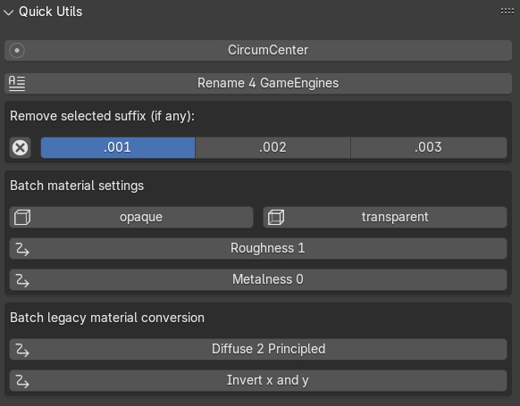
Fig. 3.8 Quick Utils panel
This panel (Fig. 3.8) permits to customize some features of the 3D objects with a series of batch processes that can assist users organize objects within the Blender file.
The CircumCenter button allows user to create a circle starting from 3 points. This function works only in edit mode and only if points are associated to the XY plane (only if they have the same Z value).
The Rename 4 GameEngines button allows to automatically modify the name of a list of selected objects by adding the prefix OB_actual name of the object, which stands for OB(JECT)_.
The Remove selected suffix (if any) tool allows user to organize the list of objects in the scene by simply removing the selected suffix (.001, .002, .003). First, to use this tool it is necessary to select the objects to be cleaned and then add the prefix OB_ by clicking on the Rename 4 GameEngine button. Second, select the suffix to be clean and then press on the X button.
The Batch material settings tool consents to automatically change four characteristics of the material of a mesh. First, select single or multiple objects. Second, select the option to change (opaque, transparent, roughness, Metalness) in the material.
By clicking on the opaque button 3DSC will change the Blend mode of the material (located in: Material Properties, Viewport Display, Settings, Blend Mode) into Opaque.
By clicking on the transparent button 3DSC will change the Blend mode of the material (located in: Material Properties, Viewport Display, Settings, Blend Mode) into Alpha mode.
By clicking on the Roughness 1 button 3DSC will change the Roughness value to 1 within the Principled BSDF node.
By clicking on the Metalness 0 button 3DSC will change the Roughness value to 0 within the Principled BSDF node.
The Batch legacy material conversion tool allows to convert a simple diffuse material into a Principles BSDF. First, select single or multiple objects. Second, press on the Diffuse 2 Principled button.
The Invert x and y button inverts the coordinates of the object’s origin. This function works only in object mode, and it does not affect the Z value.
3.5. Segmentation
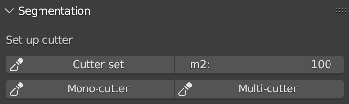
Fig. 3.9 Segmentation panel
This panel (Fig. 3.9) allows to use a set of tools to segment a 3D object in tiles. This procedure could help user to manage both the texture phase (outside of Blender) and the LODs creation of a high-resolution 3D object (such as, photogrammetric dataset or 3D scans).
Remember
Before using this tool, it’s necessary to control the scale of each 3D object that must be segmented. To control the scale of a 3D object it is recommend to check the scale value in the Scale panel, located within the Item tab, on the Sidebar of Blender. If the 3D object is the result of a 3D survey, it must match its real dimensions. If the scale values of the 3D object are not equal to 1 (in XYZ), the user must modify the scale and apply the transformation (ctrl+a -> Scale, or ctrl+a -> All transforms).
To set a regular grid, useful to segment a 3D object with the Segmentation tool, it is necessary to define the area of each tile of the grid compared with the dimension of the 3D object (to be segmented). Before generating the Cutter grid, user can adjust the extent of each tile of the grid by changing the Area value (m2) on the right side of the Set up cutter panel.
After pressing the Cutter set button, if the dimension of the grid does not correctly fit the dimension of the 3D object, user can: select all the tiles of the grid (on the outliner of Blender, every tile of the grid is automatically named as cutter followed by a consecutive number .001, such as cutter.001) and scale them using the scale command of Blender (in this case, the reference point for the scaling action is automatically placed, by the add-on, on the lower left corner of the grid). It is strongly recommended to use Top Orthographic view of Blender to set the position of the Cutter grid.
After clicking on the Cutter set button, a grid will appear in the viewport of Blender. The grid will fully cover the entire XY-plane extension of the mesh that needs to be cut. By default, the Cutter grid consists of square faces with 10-meter edges.
3.6. Tile texturing
After tiles has been created, if 3D data are related to a photogrammetric dataset processed with Metashape, the Extended Matrix Framework consents to use a semi-automatic procedure that allows to import each tile within Metashape to create a new texture.
The following steps need to be completed to use the script.
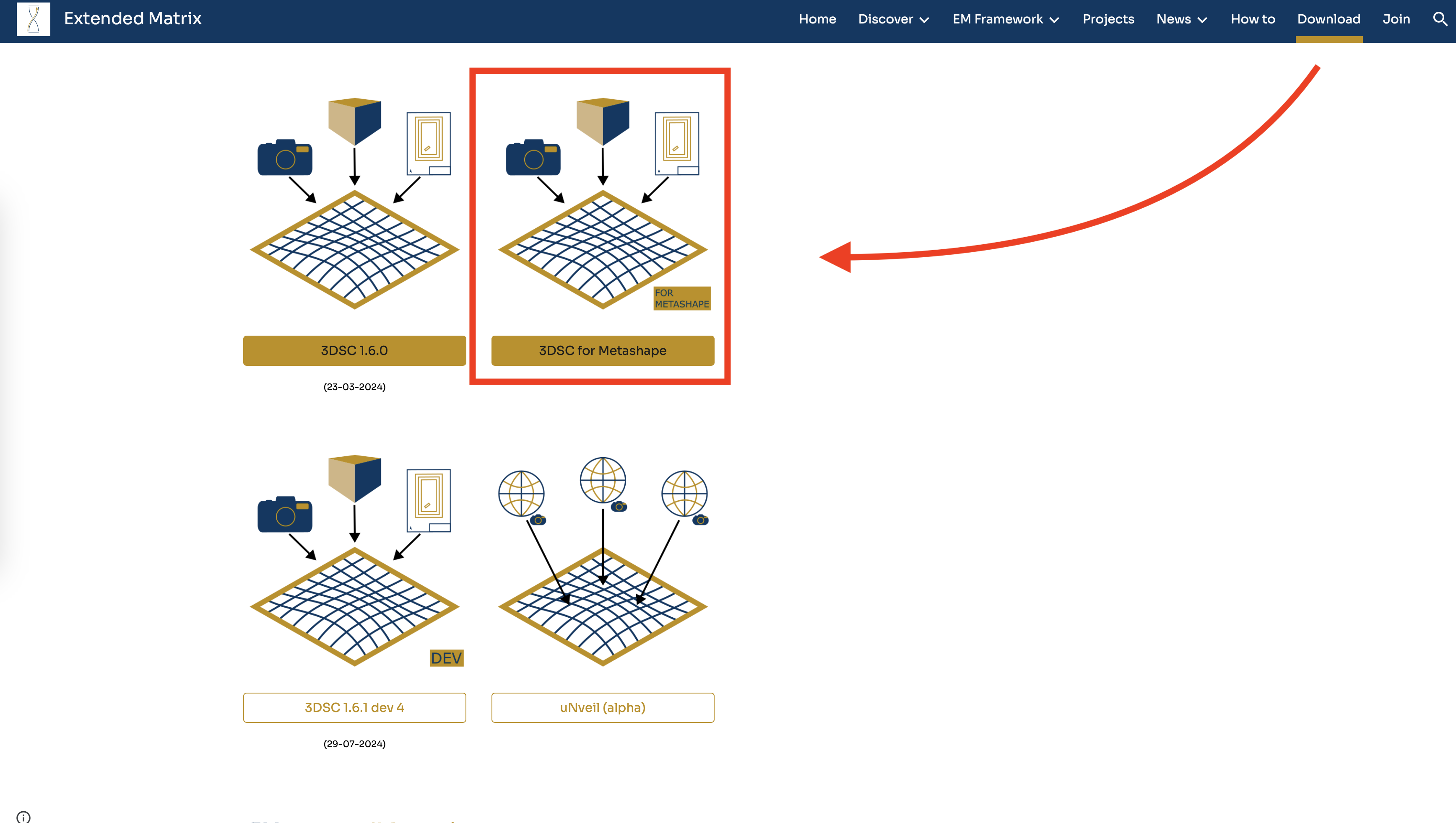
Fig. 3.10 How to reach the download button of the script 3DSC for Metashpe within the Extended Matrix webpage
Download the script (3DSC for Metashape) from GitHub. The link to the webpage of the script can be reached from the Download section of Extended Matrix website (https://www.extendedmatrix.org/download). In GitHub , to download the script the user must click on the Code green-button and press Download ZIP.
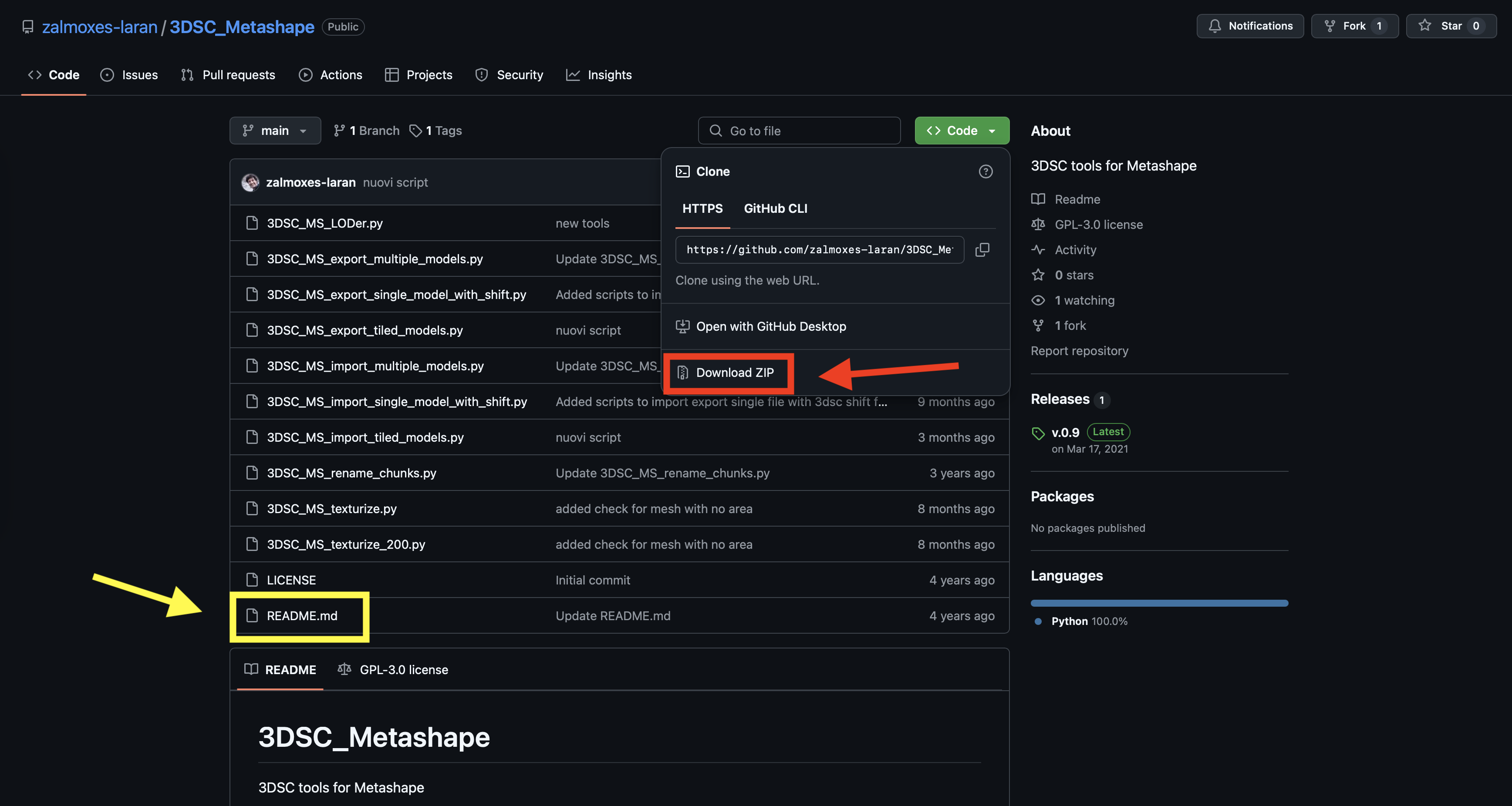
Fig. 3.11 GitHub webpage where the user can download the 3DSC for Metashape script. The red rectangle highlights the button that allows to download the zip folder of the script. The yellow rectangle highlights the file which contains instructions.
Within the unzip-folder (the user must unzip the folder to use the script) the readme.md file contains the useful instructions to correctly use the script in Metashape.
Remember
When textures are created outside Blender and may later be re-imported and modified within Blender, it is recommended to save them as .png instead of .jpg to avoid texture data loss. While this approach may increase file size (in terms of data storage), it will help preserve the quality and prevent information loss.
See also
Complete Workflow: For a complete end-to-end workflow from photogrammetry to stratigraphic annotation using LOD Generator, Segmentation, and other 3DSC tools, see Digital Replica Preparation Workflow.
3.7. LOD generator
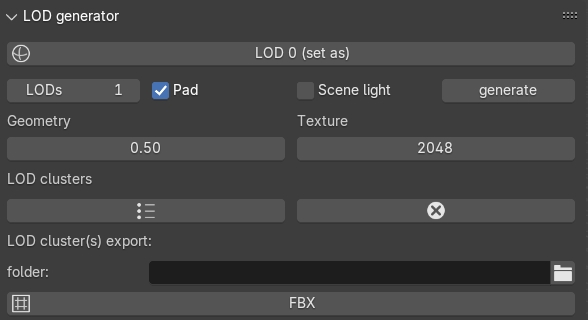
Fig. 3.12 LOD generator panel
This panel (Fig. 3.12) consents to generate Levels of Details (LODs) of a selected mesh. This type of tool helps manage large and detailed datasets, such as a mesh obtained through photogrammetry, or mesh from laser scanner.
To use this tool the user needs to first indicate the LOD0 object, that is the mesh with the highest level of detail within the .blend file. To do this, first select the object and, then press the LOD 0 (set as) button to designate it as the LOD 0 object.
Before generating LODs some steps need to be follow:
set the number of LODs by entering the correct value under the LOD 0 (set as) button;
select the Pad option to activate the Paddin ratio for LOD creation;
set the Decimation ratio;
set the Resolution of the baked texture;
indicate the path of the folder where LOD(s) will be saved.
Remember
Before closing the path window, it is recommended to uncheck the relative path option in the export window settings. Alternatively, within the export panel of 3DSC, it is possible to directly paste the entire path into the empty field and then confirm by pressing the Enter button.
After all these options have been set, pressing the generate button will create LODs in the desired folder.
If necessary, LOD generator tool permits to create a group of LODs, by clicking on the LOD clusters button, and remove it, by pressing the X button.
The FBX button allows to export LODs’ cluster in FBX format in the folder previously indicated.
3.8. LOD Manager
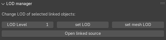
Fig. 3.13 LOD Manager panel
This panel (Fig. 3.13) consents to change the LOD for each tile related to a high-res 3D dataset (such as, a photogrammetric survey of an archaeological context), previously segmented using the Segmentation tool of 3DSC, displayed in the viewport of Blender.
By using LOD manager it is possible to visualize in Blender different tiles, related to the same 3D dataset, with different LODs.
Remember
LOD manager can be employed only if LODs have been previously generated.
The tool allows to visualize two different linked data: objects or meshes. To import linked data in Blender these simple steps must be followed:
Press File -> Link…;
Locate the .blend (all the options displayed on the right side of the window can be selected. If any issues occur, deselect the Relative Path option);
If the imported linked data do not require modifications in scale and position, select the Object folder and then select the desired objects;
If the imported linked data require modifications in scale and positions, select the Mesh folder and then select the desired meshes.
Linked data (objects or meshes) can be grouped in different collections of Blender.
By following the EM methods, these data should be stored within the same collection, for example the RB collection (that is, Reality Based collection), or in multiple collections.
Remember
It is not recommended to store linked data in sub-collections (such as, sub-RB). In that case, after setting LOD level and pressing set LOD or set mesh LOD, 3DSC will automatically display an error message and create a linked object, or mesh, within the main collection RB.
To visualize LODs related to linked object:
select a linked object;
Set the LOD value to be visualized;
press the “set LOD” button.
To visualize LODs related to linked meshes:
select a linked mesh;
Set the LOD value to be visualized;
press the “set mesh LOD” button.
This type of tool allows to manage the visualization of large datasets which have already been segmented (using the Segmentation tool). Using this tool users can view different tiles of the same 3D mesh with different LODs
Remember
This tool can be employed only if LODs have been previously generated
To visualize a specific LOD: first, select an object that has been previously processed with the LOD generator tool; second, enter the desired LOD to be visualized; third, press the set LOD button.
3.9. Model Inspector
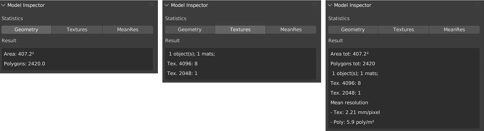
Fig. 3.14 Model Inspector panel (Geometry statistics on the left, Textures statistics in the center, MeanRes statistics on the right)
This panel consists of three main parts (Fig. 3.14): Geometry, Texture and MeanRes.
By clicking on the Geometry button the add-on returns some statistics on the geometry of the selected 3D object (area and number of polygons).
By clicking on the Textures button the add-on returns some statistics on the texture of the selected 3D object (number of materials, resolution of the texutre, number of texture per resolution).
By clicking on the MeanRes button the add-on returns a summary of all the statistical values (Geometry, Texture and MeanRes) concerning the selected 3D object (area and number of polygons, number of materials, resolution of the texutre, number of texture per resolution, mean resolution per texture - mm/pixel and mean resolution per polygons - \(poly/m^2\)).
3.10. Color Correction
This panel allows the user to apply a material color correction to one or multiple selected objects (Fig. 3.15).
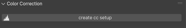
Fig. 3.15 Color Correction panel
To start the procedure, it is necessary to select one or multiple objects and then press create cc setup within the Color Correction panel.
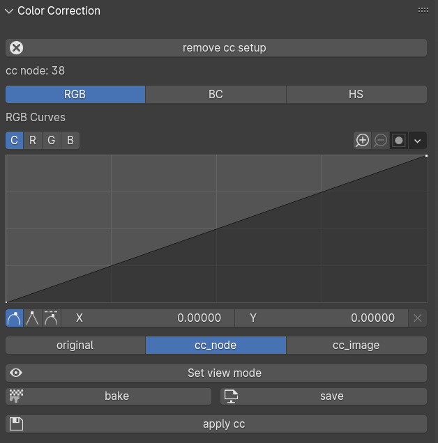
Fig. 3.16 Color Correction panel, activation of the three color profile modifiers (RGB, BC, and HS).
When the procedure is activated, the panel changes its layout (Fig. 3.16):
the remove cc setup button appears on top of the panel;
the name of the edited objects (cc node: test) is displayed below the remove cc setup button itself;
a new set of buttons complete the rest of the panel.
Three buttons (RGB, BC, HS) allow to edit the color profile of the texture material.
When RGB is pressed the RGB curve appears and it allows to easily change RGB values by moving the line within the graph (Fig. 3.16). The interaction with the curve is similar to that of a standard image editor.
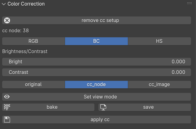
Fig. 3.17 Brightness and Constrast modifiers
When BC is pressed, the Brightness and Constrast sliders appear (Fig. 3.17).
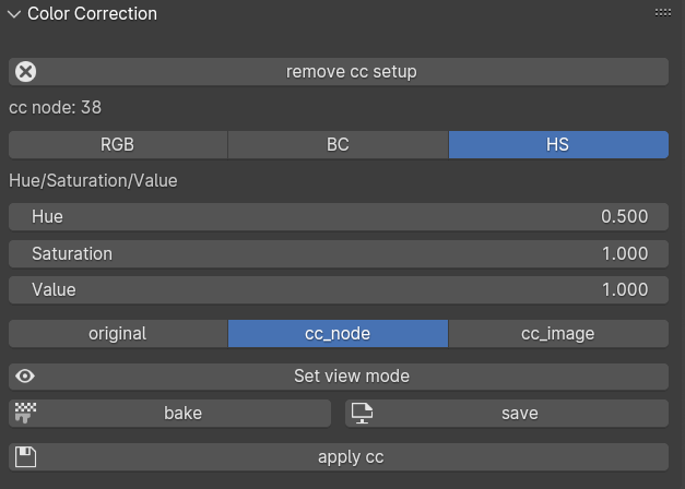
Fig. 3.18 Hue and Saturation modifiers
Similarly, when HS is pressed, the Hue, Saturation, and Value sliders are displayed at the center of the panel.
Below the RGB, BC, and HS buttons, three additional buttons allow to change the visualization of the material applied to the geometry: original displays the original material of the selected object(s); cc_node shows the material with the temporary color correction applied; and cc_image represents the final result, after baking.
To display these three temporary results, select one of the options (original, cc_node, or cc_image) and then press the Set view mode button.
The bake button allows to bake all the changes made to the original texture, using Blender’s internal bake function. These changes can be automatically saved by pressing the save button.
The apply cc button consents to use the new-modified material. In this case EM tools will automatically replace the original material with the new one.
By pressing the remove cc setup button, located at the top of the Color Correction panel, the user can easily restore the original material.
3.11. Photogrammetry paint
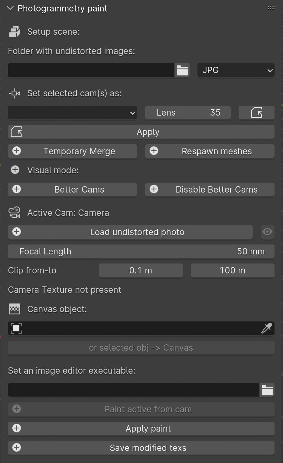
Fig. 3.19 Photogrammetry Paint panel
The Photogrammetry Paint panel in Blender is tailored for enhancing photogrammetric workflows. It provides a suite of tools for image and texture editing, enabling the user to work efficiently within the 3D environment. This panel facilitates various tasks such as:
manage undistorted images;
merge and separate meshes for texture painting;
adjust camera settings for image projection;
integrate images with external image editors for in-depth texture work.
The Setup Scene section initializes the scene for photogrammetric texture editing.
Within the Folder with Undistorted Images section the user can assign a directory to indicate where undistorted images are stored before using them during the texture painting.
The Set Selected Cam(s) As section includes several buttons:
Lens: Select the type of lens used to capture your images.
Focal Length: Input the focal length of the camera lens.
Apply: Save your configured camera settings.
Temporary Merge: Combine selected meshes for collective texturing.
Respawn Meshes: Separate previously merged meshes back to their original state.
The Temporary Merge function allows users to temporarily join two mesh objects in the scene. This feature is particularly useful for tasks that require meshes to be combined, such as texture painting to correct imperfections. For instance, users can utilize a clone stamp to transfer texture from one part of a mesh to another, effectively treating the meshes as a single unit. This can also be useful for creating a single UV unwrap atlas for multiple objects. After the necessary operations are completed, the “Respawn” button can be used to separate the meshes and return them to their original state.
The Visual Mode section inlcudes two functions: - Better Cams: Enhance camera visualization for easier editing. - Disable Better Cams: Revert to the standard camera view.
The Active Cam section displays the camera that is currently being used for editing. This part of the panel presents three important functions:
Load Undistorted Photo: Load the undistorted image for the active camera, ready for texture painting.
Focal Length/Clip from-to: Fine-tune the active camera’s focal length and clipping range for precise texture projection.
Camera Texture Not Present: Notification when a camera texture is missing.
Canvas Object section allows to simply select the object which will receive the projected textures.
The Set an Image Editor Executable section permits to specify the path to an external image editor for advanced texture editing.
Within the Post-Processing in External Image Editors section it is possible to apply and save the final result.
After pressing the Paint Active from Cam button, the user engages in a post-processing phase, typically in an external image editor such as GIMP or Photoshop. Here is what generally occurs during this phase witihn GIMP/Photoshop:
Open Image Editor: GIMP or Photoshop launches with two instances; one displaying the active camera’s view and the other showing the undistorted image.
Copy/Paste Textures: * Use CTRL+A and CTRL+C to select and copy the entire undistorted image. * Paste it onto the canvas that represents the 3D model.
Clone Brush Tool: Utilize the clone brush to remove unnecessary parts of the photograph and make chromatic adjustments. This ensures that the newly applied texture blends seamlessly with the existing textures.
Finalizing Texture: Once the texture editing is complete: * Disable the background layer in the image editor to isolate the new texture. * Save the new texture by overwriting the existing file or as a new file to be used as a patch.
Apply New Texture in Blender: Back in Blender, the Apply Paint function transfers the edited texture onto the 3D model.
Save and Update Model: Hit Save Modified Textures to save your changes, solidifying the improved texture on the model.
Remember
It’s important to periodically save your work in the external editor and keep track of version changes to ensure a smooth workflow.
Leverage the Photogrammetry Paint panel to ensure your textures align perfectly with the undistorted images, creating high-quality, realistic 3D models.