Texture Smart Mapping (TSM)
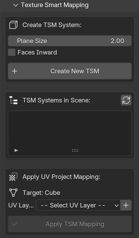
Fig. 64 Texture Smart Mapping panel
The Texture Smart Mapping (TSM) panel (Fig. 64) is a dedicated root-level panel in the 3DSC sidebar. It provides an efficient workflow for applying texture projections to 3D meshes using a standardized cubic projection system with 6 oriented planes.
This tool is particularly useful for:
Rapid texture mapping of architectural elements
Standardized UV projection workflows
Multi-object texture application with consistent projection settings
Managing multiple texture mapping configurations in the same scene
Creating a TSM System
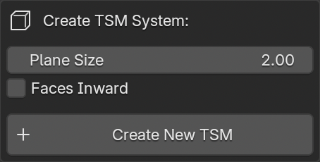
Fig. 65 TSM creation options
To create a new TSM system (Fig. 65):
Select an object in the 3D viewport (can be an empty object or any mesh)
Set the desired parameters:
Plane Size: Defines the size of each projection plane in meters (default: 2.0m)
Faces Inward: Checkbox to orient projection faces toward the center (inward) or outward
Click the Create New TSM button
The operator will automatically:
Create a new empty object named
TSM_XX(with automatic numerical suffix)Generate 6 plane objects (top, bottom, front, rear, left, right) parented to the TSM empty
Position and orient the planes correctly to form a cubic projection setup
Maintain the location, rotation, and scale of the originally selected object
Add the new TSM to the system list
Technical Details
TSM systems are identified by a custom property
tsm_system = TrueEach plane is exactly positioned at
plane_size/2distance from the TSM centerAll planes maintain a scale of (1.0, 1.0, 1.0) to avoid UV distortion
The system correctly handles any rotation of the source object
TSM Systems List
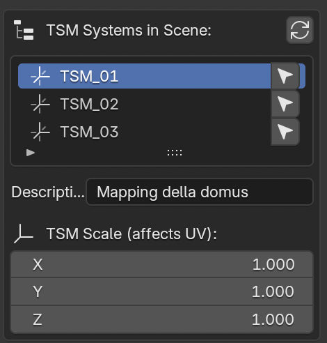
Fig. 66 TSM systems management
The TSM systems list (Fig. 66) displays all available TSM systems in the current scene.
List Features:
Refresh Button: Manually updates the list to detect new or removed TSM systems
Auto-refresh: The list automatically updates after creating a new TSM
Select Icon: Selects the corresponding TSM empty object in the 3D viewport
Per-TSM Information:
Description Field: Editable text field to add descriptive information (e.g., “Mapping for Severan period buildings”)
Automatically saved as custom property
tsm_descriptionon the TSM empty objectUseful for organizing multiple TSM systems with different purposes
TSM Scale: Displays and allows editing of the X, Y, Z scale values
Directly affects the UV projection scale
Modifying scale values updates the projection in real-time
Useful for fine-tuning the texture mapping without recreating the system
Remember
Editing the TSM scale values will automatically influence the UV projection scale on all meshes using that TSM system.
Applying UV Project Mapping
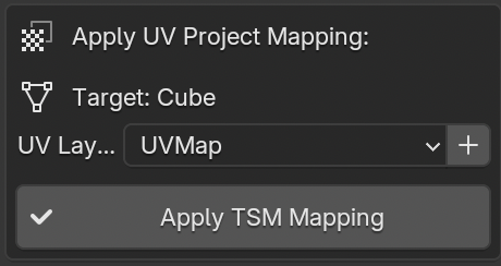
Fig. 67 UV Project mapping application
The Apply UV Project Mapping section (Fig. 67) allows users to apply the selected TSM projection system to mesh objects.
Workflow:
Select a TSM from the list above
Select a mesh object in the 3D viewport (the target object is displayed in the panel)
Choose or create a UV layer:
Use the dropdown menu to select an existing UV layer
Click the + button to create a new UV map with a custom name (default: “TSM_UVMap”)
Click Apply TSM Mapping
UV Layer Management:
The panel automatically detects all UV layers present in the selected mesh object. If no UV layers exist, the panel displays a warning and provides the option to create one.
The Add New UV Map operator:
Opens a dialog to specify the UV map name
Creates the new UV layer
Automatically selects it in the dropdown menu
Sets it as the active UV layer
Important
If the mesh object already has a UV Project modifier, the operator will display a warning and skip the operation to prevent conflicts.
Technical Implementation
Modifier Configuration:
When applying a TSM system to a mesh, the operator:
Creates a new UV Project modifier named
TSM_UVProject_[TSM_name]Sets the
projector_countproperty to 6Assigns the 6 planes (top, bottom, front, rear, left, right) as projectors
Links the modifier to the selected UV layer
Maintains default modifier parameters (Aspect X, Aspect Y, Scale X, Scale Y)
Projector Assignment:
The 6 planes are assigned to the UV Project modifier in the following order:
Top (plane facing +Z local axis)
Bottom (plane facing -Z local axis)
Front (plane facing +Y local axis)
Rear (plane facing -Y local axis)
Right (plane facing +X local axis)
Left (plane facing -X local axis)
This arrangement ensures complete coverage of the mesh from all cardinal directions.
Use Cases
Architectural Documentation:
The TSM system is particularly effective for documenting architectural elements where orthogonal projections are required:
Wall faces and facades
Floor and ceiling surfaces
Column capitals and bases
Architectural details requiring precise texture placement
Archaeological Objects:
For archaeological artifacts with approximately cubic or box-like proportions:
Stone blocks and ashlars
Sarcophagi and altars
Architectural fragments
Sculptural reliefs
Multi-Phase Workflows:
TSM systems can be organized by:
Chronological phases: Create separate TSM systems for different historical periods (e.g., “Republican period mapping”, “Imperial period mapping”)
Material types: Different projections for stone, brick, stucco surfaces
Documentation campaigns: Organize by survey date or acquisition method
Best Practices
Use descriptive names in the TSM description field for easy identification
Adjust TSM scale values to match the actual dimensions of the surveyed elements
Create multiple TSM systems with different scales for objects at different detail levels
Position TSM empties at the center of the target objects for optimal projection
Complete Workflow Example
Scenario: Texturing a virtual reconstruction with chronologically-consistent building orientations
When modeling a virtual reconstruction, it is common practice to texture entire groups of buildings that share a particular orientation, typically related to the chronological period of the monuments. Changes in historical periods often correspond to changes in urban orientation and alignment.
Case Study: Republican and Imperial phases of a Roman archaeological site
Analysis Phase:
Identify buildings with Republican-era orientation (e.g., aligned North-South at 15° deviation)
Identify buildings with Imperial-era orientation (e.g., aligned with the later street grid at 8° deviation)
Note that each chronological phase has distinct architectural alignments
TSM Creation for Republican Phase:
Create an empty object at the site center
Rotate the empty to match the Republican-era building orientation (15° deviation)
Set plane size to 5.0 meters (appropriate for typical building facade height)
Keep “Faces Inward” unchecked
Click “Create New TSM”
Add description: “Republican phase - North-South orientation 15°”
TSM Creation for Imperial Phase:
Create another empty object
Rotate to match the Imperial-era street grid orientation (8° deviation)
Set plane size to 6.0 meters (larger Imperial buildings)
Click “Create New TSM”
Add description: “Imperial phase - Street grid orientation 8°”
Applying Textures to Republican Buildings:
Select first Republican-era building mesh
Create UV map named “TSM_Republican”
Select the Republican TSM from the list
Click “Apply TSM Mapping”
Repeat for all Republican-era structures
Applying Textures to Imperial Buildings:
Select first Imperial-era building mesh
Create UV map named “TSM_Imperial”
Select the Imperial TSM from the list
Click “Apply TSM Mapping”
Repeat for all Imperial-era structures
Period-Specific Fine-tuning:
Adjust Republican TSM scale for smaller, earlier construction techniques
Adjust Imperial TSM scale for larger, monumental architecture
The UV projections update automatically across all buildings using each system
Advantages of this Approach:
Consistent texture orientation within each chronological phase
Easy to modify all buildings of a specific period simultaneously
Clear documentation of which buildings belong to which phase
Efficient workflow for large-scale virtual reconstructions
Supports the Extended Matrix methodology for stratigraphic reconstruction
Best Practice for Virtual Reconstructions
Create distinct TSM systems for each chronological phase or building orientation in your reconstruction. This approach maintains consistency within each period while clearly distinguishing between different historical layers. The TSM description field becomes a valuable tool for documenting the chronological attribution of building groups.
Additional Notes
Performance Considerations:
TSM systems are lightweight (empty object + 6 simple planes)
Multiple TSM systems can coexist in the same scene without performance impact
UV Project modifiers are evaluated efficiently in Blender’s modifier stack
Compatibility:
TSM systems work with any Blender version supporting UV Project modifiers (2.80+)
Compatible with other modifiers in the stack
Can be used in conjunction with other 3DSC tools (LOD generation, texture patching, etc.)
Limitations:
Only one UV Project modifier per mesh is supported by the operator (to prevent conflicts)
Best results are achieved with approximately cubic or box-shaped geometries
For complex organic shapes, manual UV unwrapping may be more appropriate
Remember
TSM systems are non-destructive. The modifier can be disabled or removed at any time, and the original mesh geometry remains unchanged.