Shifting
See also
This page is the parameter reference for the Shifting panel. For the rationale behind coordinate shifting (why georeferenced data needs an origin offset in Blender), see Coordinate shifting in 3DSC.
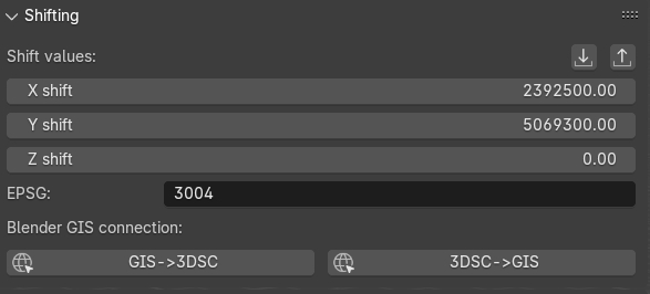
Fig. 39 Shifting panel
This panel (Fig. 39), which is directly linked to the Importers panel, represents the shifting values (expressed with X, Y, Z) of an object (for example a 2D/3D survey) imported in Blender. Shifting values indicate the translation of an imported 2D survey or 3D object respect to absolute coordinates. On the lower part of the panel, the line EPSG indicates the Reference System (RS) whom 2D and 3D objects, imported in the Blender file, will refer to.
Remember
In order to visualize georeferenced 3D models in Blender, as the ones obtained with photogrammetry, it is strongly suggested to export them with the same shift used in 3DSC and BlenderGis.
To insert shift values in Blender two modes are available: manual and automatic.
Manual mode implies that user insert manually both the coordinates and the EPSG code.
On the contrary, Automatic mode (RECOMMENDED) implies that a SHIFT.txt file is automatically read by 3DSC (ONLY if the file is placed in the folder where the .blend file is saved) and, instantly, shift coordinates will appear within the Shift values lines. To use this automatic mode, press the import shift coordinated from file, on the right corner of the panel, and locate the SHIFT.txt file.
Remember
The SHIFT file is a simple .txt file which contains only one line of data (EPSG:: code X Y Z) here an example:
EPSG::3004 2392800.00 5069900.00 0
By pressing the Export Shift values button, the shift panel allows to export shift coordinates (.txt format) for different purposes.
In order to easily use georeferenced data within Blender it is necessary to set the same SHIFT coordinates also in BlenderGIS (RECOMMENDED). As already mentioned for 3DSC, this important step for BlenderGis can be accomplished in two ways: manual and automatic.
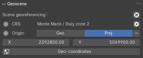
Fig. 40 The Geoscene panel of BlenderGIS
Manual mode implies that user manually inserts data (coordinates and EPSG) within the Preferences of BlenderGIS. Then, to confirm this information, user must set the RS and the shift coordinates in the View tab, located on the Sidebar of Blender, within the panel Geoscene (Fig. 40). In the Preferences of BlenderGis, before setting the shift coordinates, user must set the correct RS by pressing the add button.
Automatic mode involves the use of an automatic procedure that imports shift data from 3DSC to BlenderGIS. In the Shifting panel of 3DSC, it is possible to activate this option by pressing the 3DSC->GIS button. At the end of this process, it is recommended to control in the Geoscene panel, located in the View tab of the sidebar of Blender, if data are correctly inserted.
If SHIFT coordinates have been previously set up in BlenderGIS, by pressing the GIS->3DSC button all the SHIFT data will be setting up in 3DSC.
Remember
Before saving the file, it’s recommended to check if SHIFT data are synchronized between 3DSC and BlenderGIS.
After shift data has been correctly inserted and an empty Blender file has been setting up and saved, user can easily import georeferenced data by using both 3DSC or BlenderGIS import options.